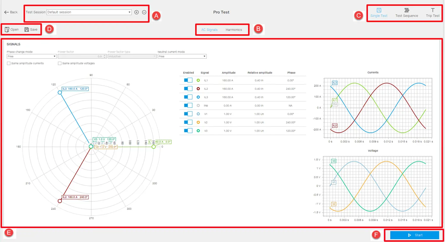
Description The Single Test in Test Execution or Pro test allows you to simulate manually customized current and/or voltage values.
What it looks like
Part
Function
Back
Returns to the main page of the Test area function.
Open
Opens a test on the page that was previously downloaded and saved on the PC.
Save
Saves the test to the PC in .test format. Note: the .test format is a proprietary format that can only be read with Ekip Connect.
A
Indicates the session and title of the open test. "+" button for adding a new test session, "-" button to delete selected session.
B
Select the tab Signals or Harmonics
C
Area to select test type to be executed
D
Test Configuration dashboard
Start
Starts the test
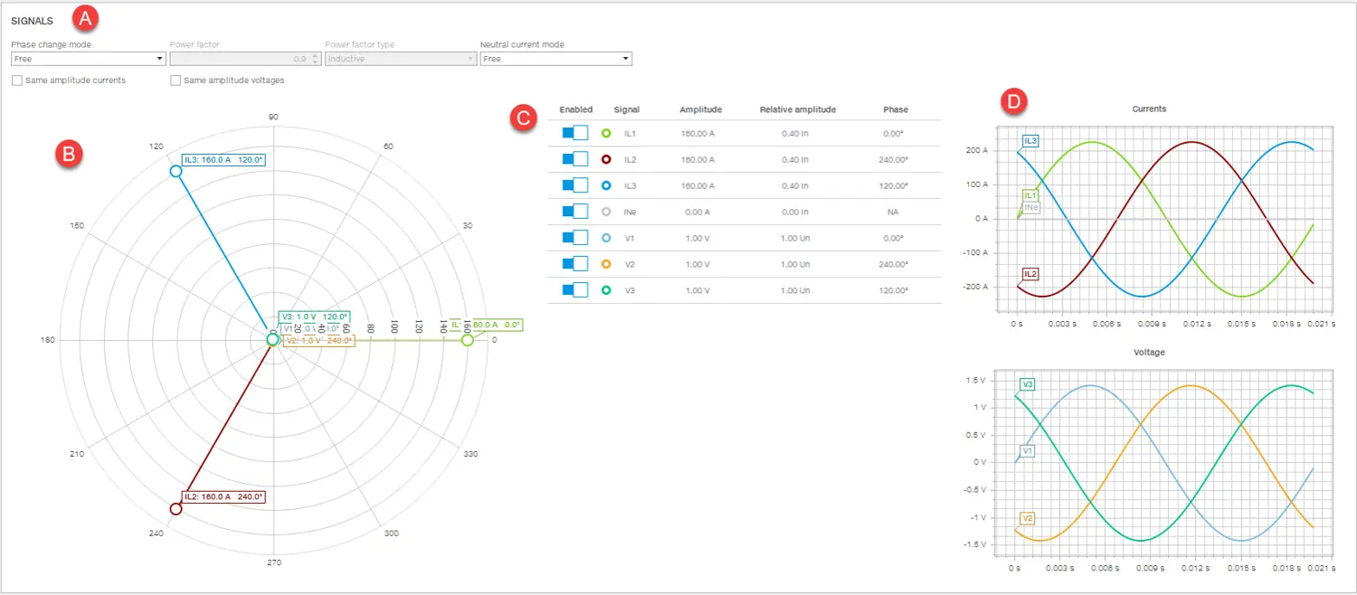
Tab Signals
Part
Description
A
Signal settings, e.g. load type (inductive or capacitive), power factor.
B
Phasor diagram: displays and allows changes to be made to the phase shift and amplitude of the phasors of the signals to be simulated during the test. Just drag the end of a phasor to modify the diagram.
C
Signals table: displays and allows you to change the numerical value of the amplitude and phase difference of the fundamental component of the test signals. Amplitude can be expressed both in relative (rated current/voltage) and absolute terms (Amperes/Volts).
D
Graphs of currents and voltages based on the settings in the phasor diagram or signal table.
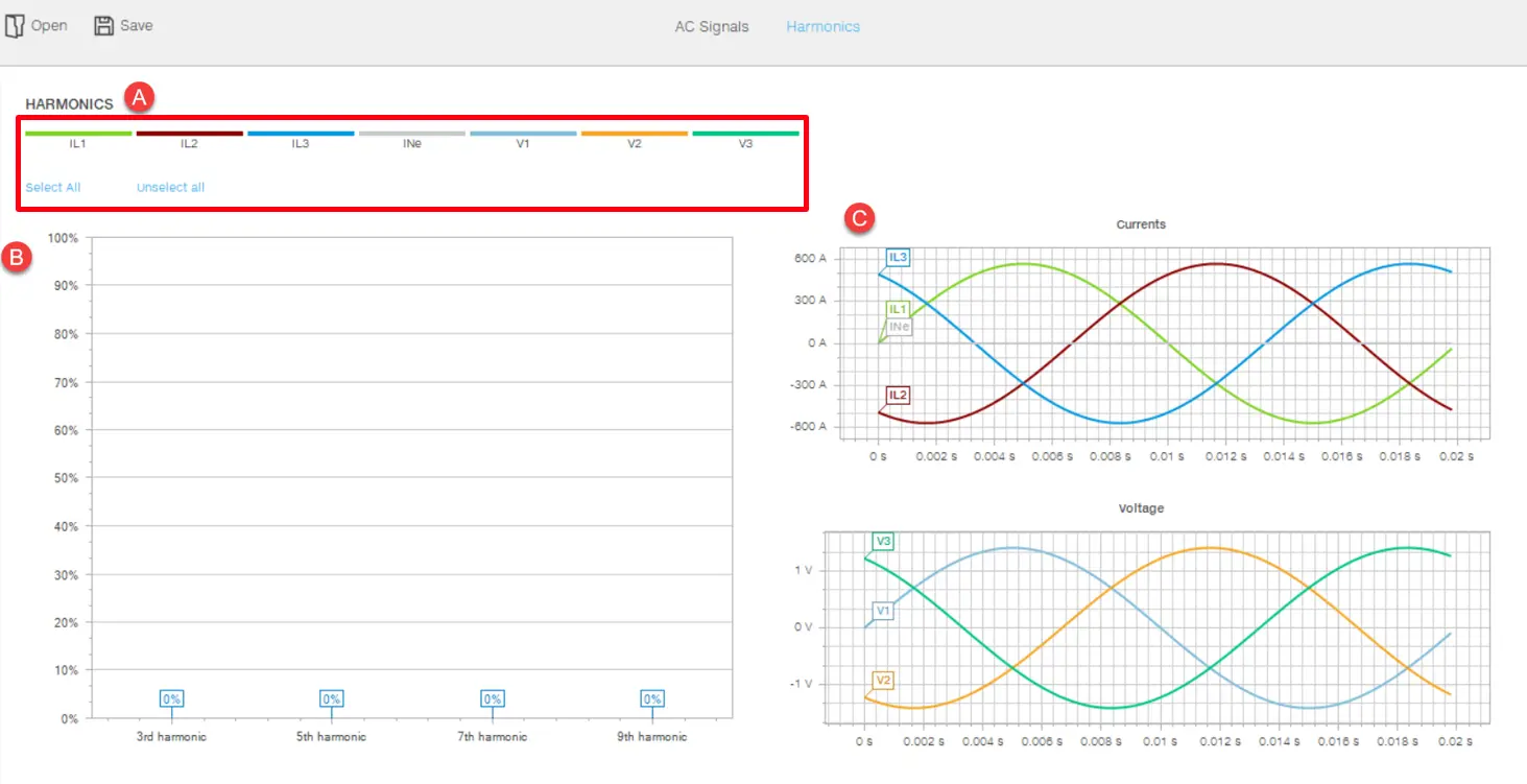
Tab Harmonics
Part
Description
A
Area for selecting/deselecting the current phase or voltage for which the amplitude of the harmonic components is to be changed
B
Harmonics diagram: displays and modifies the amplitude of the 3rd, 5th, 7th, and 9th harmonic component of the AC test signals. Just drag a point of the harmonic to modify the diagram.
C
Graphs of currents and voltages based on the settings in the harmonics diagram.
Start manual test
CAUTION! Perform the test with no current flowing
With the device connected and communicating with Ekip Connect, click on Tools > Test area > Test Execution > Single Test. If you wish to perform tests on a Sace Emax 3 device, click on Tools > Test area > Pro Test > Single Test.
If required, create or select the session in which to perform the test (Create a test session).
Click on Run test: the test page opens.
Customize the values in tabs Signals and Harmonics according to the device configuration and the conditions to be tested.
Click on Start: the signals are sent to the protection release and a window showing the progressive status of the test opens.
The release may generate a trip, depending on how it has been configured.
Note: none of the parameters can be edited during the test.
To interrupt the test, click on Stop.
To view the report, click on View test report: the test report appears.
If required, export the data in .xlsx format, download in .pdf format or print the report.

 CAUTION! Perform the test with no current flowing