Read the previous article
Power Controller: useful information
Skip to main content
Skip to menu
Skip to footer


Ekip Connect
Everything in view, all under control
Select your language
Select your language
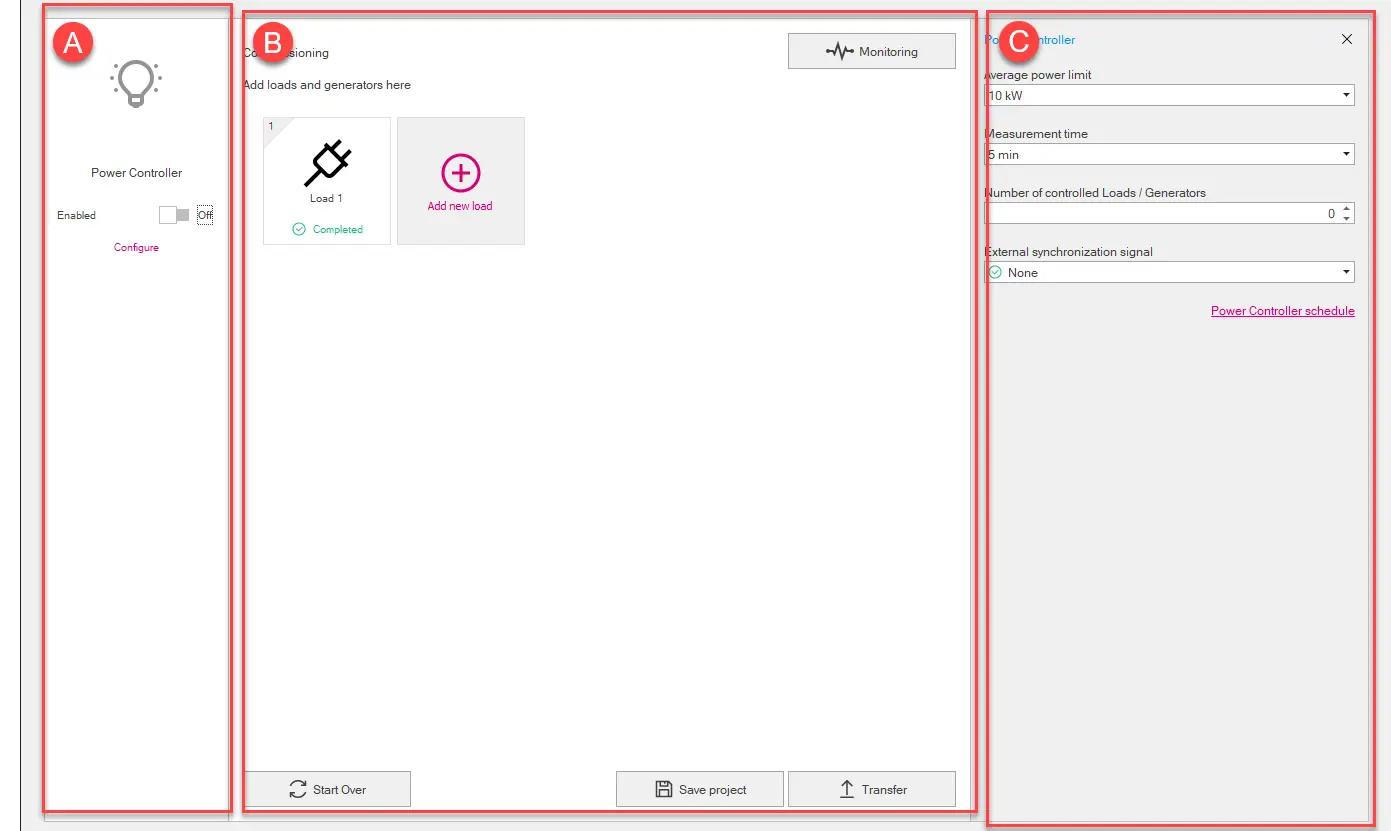
Power Controller: what it looks like
Page Design

Part | Description |
|---|---|
| A | Function Power Controller area. It contains the following elements:
|
| B | Loads area. It contains the following elements:
Note: the .pwc format is a proprietary format that can only be read with Ekip Connect.
|
| C | Area for the parameters of the element selected in [A] or in [B] (Power Controller: parameters). (only if selected Power Controller in [A]) Button to open the Window Power Controller programming |
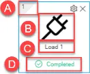
Graphical representation of the load

Part | Description |
|---|---|
| A | Assigned disconnection priority |
| B | Icon selected for the load |
| C | Name assigned to the load |
| D | Load configuration status:
|
 | Button for customising the load icon To display the button, position the mouse pointer over the graphic representation of the load. To display the button, position the mouse pointer over the graphic representation of the load. |
 | Button to delete the load To display the button, position the mouse pointer over the graphic representation of the load. To display the button, position the mouse pointer over the graphic representation of the load. |
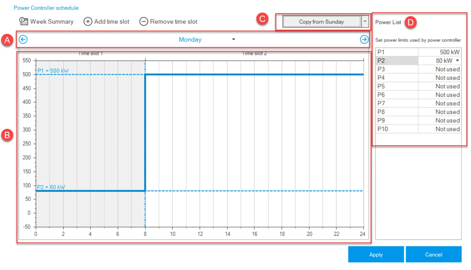
Window Power Controller programming

Part | Description |
|---|---|
| Week summary | Button to show/hide in [B] the programming of the entire week. In this view, programming cannot be changed. |
| Add time slots | Button to add a time slot to the programming. To define a slot, select and drag the blue line at the chosen power value (Y-axis) and time value (X-axis) with the mouse. To define a slot, select and drag the blue line at the chosen power value (Y-axis) and time value (X-axis) with the mouse. |
| Remove time slot | Button to remove the last added time slot from the programming. |
| A | Commands to select the day of the week to be displayed and buttons to scroll through the days. |
| B | Programming display area.
|
| C | Command to define the programming of a day based on the programming of another day. To perform the command, select the day from which to copy the programming from the list and then click the button. To perform the command, select the day from which to copy the programming from the list and then click the button. |
| D | List of defined power limits. Up to 10 power limits can be set. |
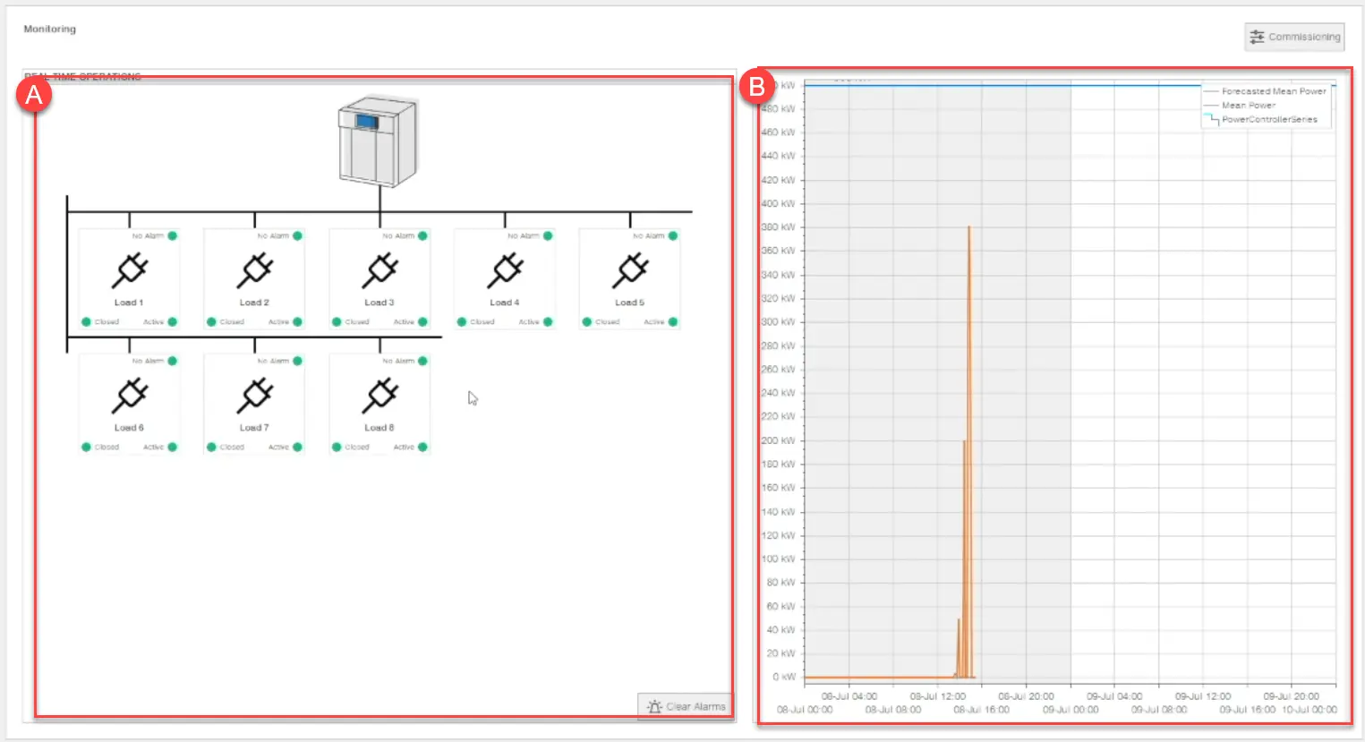
Page Monitoring

| Part | Description |
|---|---|
| Commissioning | Button to access the Design page (Page Design) |
| A | Load status area.
Button Clear Alarms to rest the alarms of all the loads. |
| B | Graph: time (X-axis) and power (Y-axis). Displays the power limit value set for that period, the average power value recorded and the estimated average power value. |