Read the previous article
Embedded ATS
Skip to main content
Skip to menu
Skip to footer

Description of the tool
Description of the function
Interface Protection System in Ekip Connect

Ekip Connect
Everything in view, all under control
Select your language
Select your language
Interface Protection System
Description of the tool
The IPS Interface Protection System function allows faults to be managed in installations which are able to function thanks to the energy produced by renewable and local energy sources, especially the absence of power supply, e.g. due to a fault on the MV voltage side.
The function conforms to standard CEI 0-16.
Description of the function
Interface Protection System is a function that monitors installations in real time that can operate with energy from renewable and local energy sources. If there is a malfunction in the electrical network, in particular a power failure, the function protects the installation.
Two scenarios are handled:
- device as main grid circuit breaker (relay auto-reclosing configuration not available).
- device as local generator circuit breaker (relay auto-reclosing configuration available).
The function conforms to standard CEI 0-16.
>> For details on the Interface Protection System function, please refer to documents 1SDH002043A1001-C available here and 1SDH002129A1002 available here.
Interface Protection System in Ekip Connect
From Ekip Connect the following operations can be performed:
- quickly configure the function, i.e. installation settings, settings for protection devices, inputs and outputs
Requirements
Access to the function | Unrestricted |
Type of devices that support the function | Ekip UP, EkipUP+ |
| Device status | Any to configure the function and save the configuration. Connected and communicating to transfer the configuration to the device. Note: it is recommended to keep the circuit breaker in the open state during the transfer. |
| Type of connection with the device | Local connection: connection via Ekip T&P Remote connection: Ekip COM TCP/Ekip COM RTU communication module |
>> For more details on supported devices and requirements for each, please refer to document 9AKK108467A9238 available here.
What it looks like
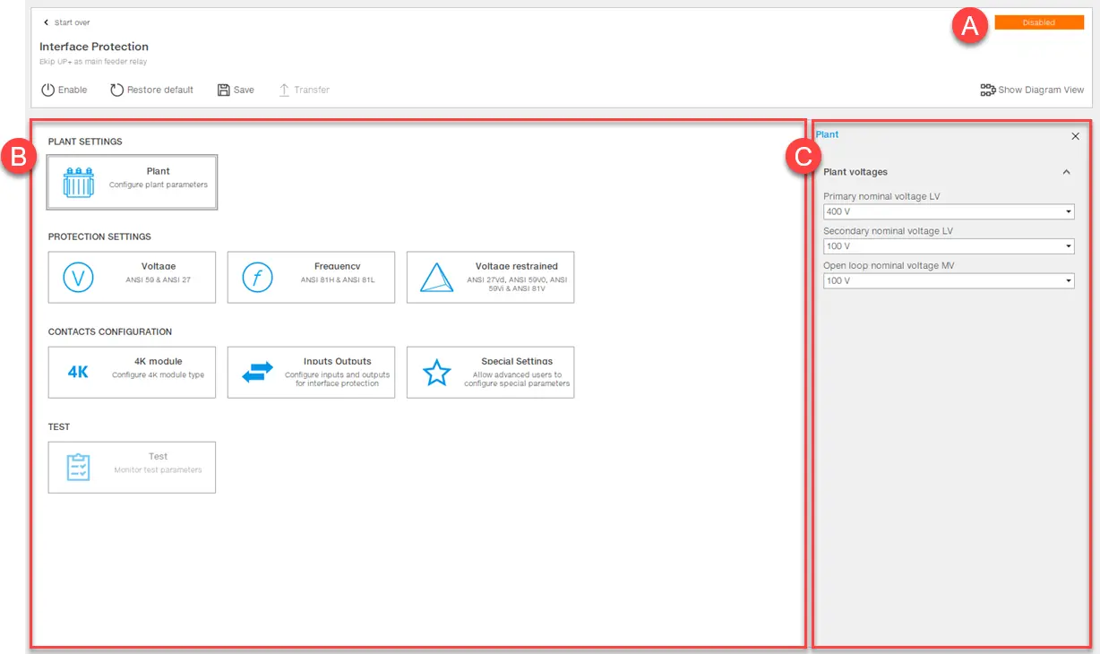
Note: the following image refers to the page that is visible with an open/new project. See Configure the function Interface Protection System.

Part | Description |
|---|---|
| Breakdown | Button to open another project or create a new project. |
| Enable/Disabled | Button to enable/disable the function. The current status is displayed in [A]. |
| Reset default | Button to reset parameters to factory settings. |
| Save | Button to save the project on the PC in .ips format. Note: the .ips format is a proprietary format that can only be read with Ekip Connect. |
| Transfer | Button to transfer the configuration to the device |
| Show diagram view/Show tile view | Button to change the view of the area [B]. |
| A | Function status |
| B | Elements area to be configured in tile view (default) or in diagram view. |
| C | Area for the parameters of the element selected in [B]. |
Configure the function Interface Protection System
- Click on Tools > Interface Protection System.
- To start a new project, select the device type and then the button for the function that the device performs, or click on Open project to open a previously saved project.
- On the page displayed, in the area of the elements to be configured (see What it looks like), select the element to be configured and set the parameters.
- Click on Enable to enable the function.
- To transfer the configuration to the device, click on Transfer.
Note: to transfer the configuration to the circuit breaker, it is recommended for the circuit breaker to be in an open state.
- As also stated in the message that appears on the page, check that the device is receiving the status of the circuit breaker correctly, i.e. that in the absence of voltage, input 01 of the Ekip Signaling 4k module is on, and click on Yes: at the end of the transfer, a .pdf file containing the configuration report can be downloaded.