The Custom Logic tool lets you create your own logics for various applications between devices with the purpose of saving time on complex programming and extra wiring, and removing the need for external controllers.
The most significant capabilities that the tool possesses are as follows:
The connection to circuit breakers during programming is not required, ensuring the comfort and safety of the operator.
Creation of flexible logics using a block-based visual approach on a canvas.
Logic validation system to minimize user error.
Requirements
Access to the function
Unrestricted. For transfer to the device, package Custom Logic is required, which can be purchased and activated on Marketplace.
Type of devices that support the function
Circuit breaker Emax 3
Device status
Any, to configure the function and save the configuration. Connected and communicating to transfer the configuration to the device. Note: it is recommended to keep the circuit breaker in the open state during the transfer.
Type of connection with the device
Local connection: connection via USB Type-C
Create a Custom Logic project
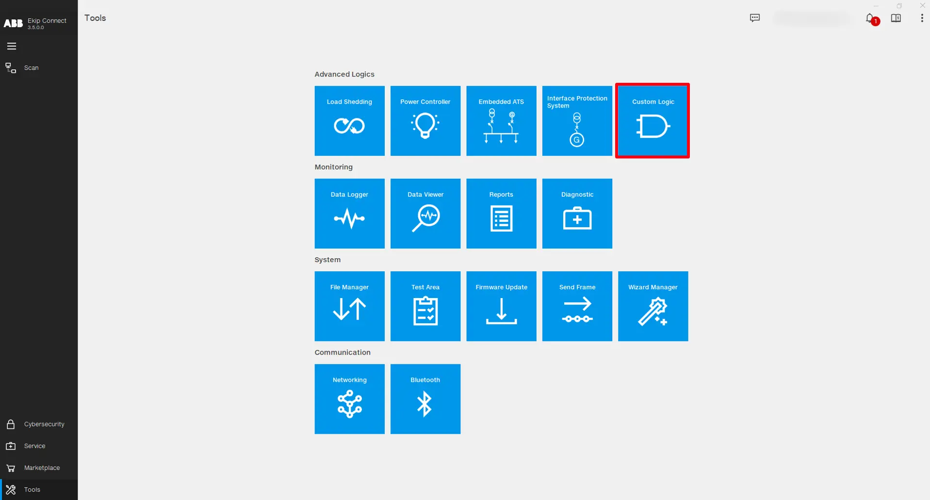
Open the Ekip Connect software and click on Tools -> Custom Logic.
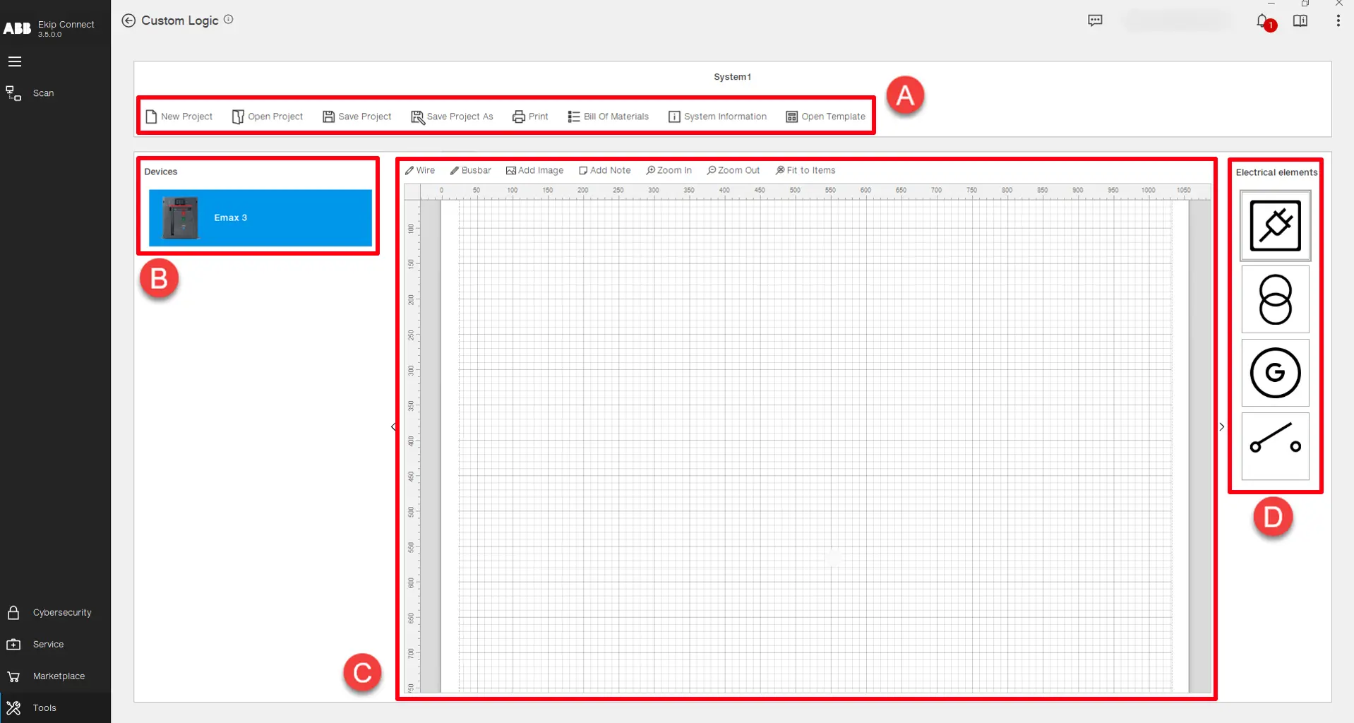
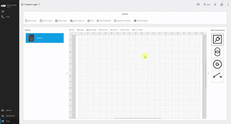
The tool's main page serves the purpose of plant level design of the logic in which the devices involved in the customized logic are inserted in a schematic view. Also the file management of the project is done at this level:
Part
Description
A
Functionalities used for project and file management: • New Project -> Start a new project.
• Open Project -> Open an existing project.
• Save Project -> Save the project in an existing project file.
• Save Project As -> Save the project in a new project file.
• Print -> Print a document containing all the information and materials of the project.
• Bill Of Materials -> List of materials classified in hardware, software and trip unit types, that are required to guarantee the correct functioning of the logic on the device.
• System Information -> Displays the history of all the downloads and uploads of the logic for the devices present in the project.
• Open Template -> Opens a list of preconfigured logic projects that can be uploaded directly to the devices. (Coming Soon)
B
List of devices that can be involved in the logic. Double click on the device or drag and drop it on the canvas to insert it in the project.
C
Project canvas -> Used to graphically represent the custom logic project. It is possible to draw a single line diagram of the plant or a schematic that can assist to better understand the entire system. There are several options to edit on the project canvas:
• Wire -> Draws a line and connection between objects.
• Busbar -> Draws a thicker line and connection between objects.
• Add Image -> Inserts an external image.
• Add Note -> Inserts a sticky note.
• Zoom In, Zoom Out & Fit to Items -> Adapt the graphic view of the elements on the project canvas.
Note: The project designed on the canvas is just a graphic representation and it does not define any behavior of the logic.
D
List of electrical elements that can be added in the project canvas. Double click on the element or drag and drop it on the canvas to insert it in the project.
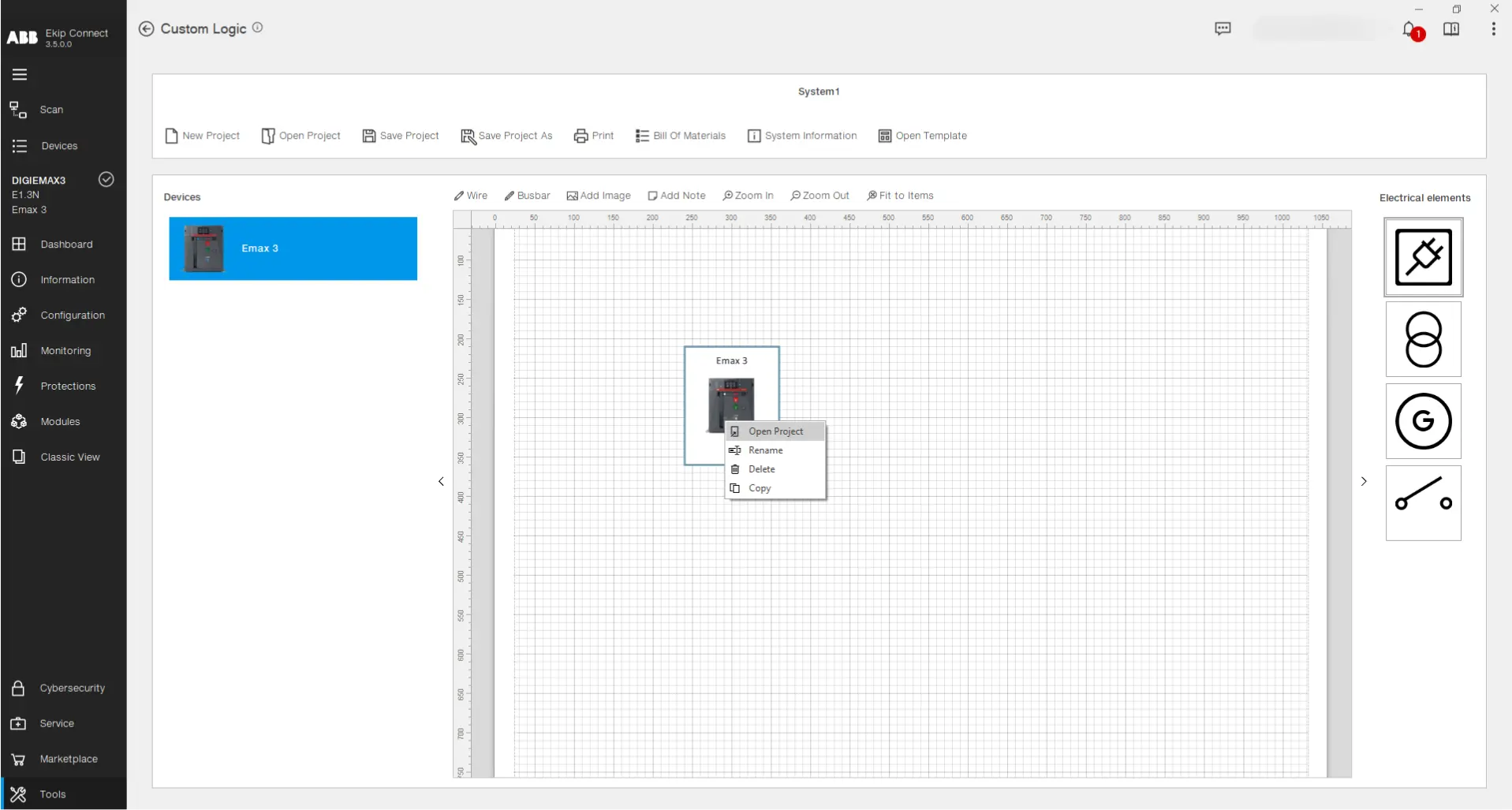
To create a logic for a device, drag and drop on the project canvas a device from the list. Then right click on it and select the "Open Project" command (or double left click on the device image):
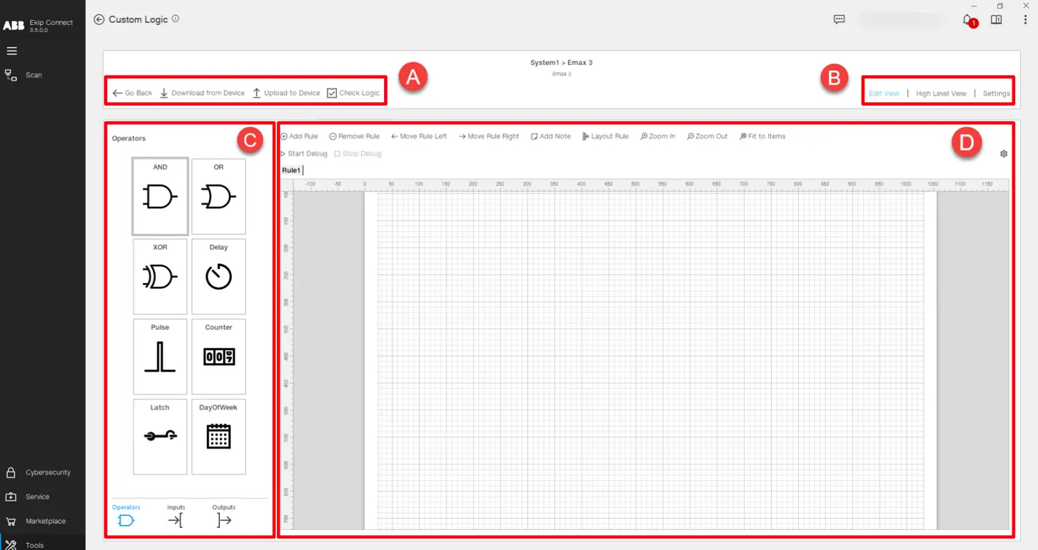
Now the programming page is opened. Inside this view it is possible to implement the logic for the device selected:
Part
Description
A
Logic design functionalities:
• Go Back -> Goes back to the main page.
• Download from Device -> Reads the logic present on the connected device for the user to view and edit.
• Upload to Device -> Transfers the designed logic to the connected device.
• Check Logic -> Performs a series of checks on the logic designed in terms of the syntax used and the memory constrains of the device.
B
Logic design views:
• Edit View -> Shows the main programming canvas used to design the logic.
• High Level View -> Shows the entire logic designed, emphasizing the interconnections between the logic blocks.
• Settings -> Shows the list of Programmable Status, Physical Outputs and Monitor Delays programmed in the current logic.
C
Logic components:
• Inputs -> List of variables that can be used as an input signal state for a logic block.
• Operators -> List of blocks containing computation functions applied to one or more inputs with the purpose of providing an output signal.
• Outputs -> List of output signals grouped in "Ekip Signalling" digital outputs, generic "PLC Out" outputs and internal "Temporary" outputs.
Drag and drop or double left click on a component to insert it in the programming canvas.
D
Programming canvas -> Used to design the logic for the chosen device. The main principle of design are the "Rules", representing small logic blocks, the combination of which creates the logic to be transferred in the device. At the top of the canvas, there are various functionalities:
• Add Rule -> Inserts a new rule in the logic.
• Remove Rule -> Deletes the selected rule.
• Move Rule Left, Move Rule Right -> Edit the positioning of the rules in the logic.
• Add Note -> Inserts a sticky note in the rule.
• Layout Rule -> Organizes automatically the layout of the rule, optimizing space in the canvas.
• Zoom In, Zoom Out & Fit to Items -> Adapt the graphic view of the elements on the programming canvas.
• Start Debug -> Starts an offline simulation used to test the logic created without having to transfer it to the device. The user can click on the inputs to give them a value and observe how the outputs behave.
• Stop Debug -> Stops the simulation.
• Debug Settings -> Used to set the time step of the simulation and the stop time.
For more details and a thorough walk through of the tool, please consult the complete user manual of the custom logic tool, downloadable down below:
The ATS Template is a high-performance energy automation solution that is easy to install and configure and is programmed in the devices by using the Custom Logic Tool. Its purpose is to provide ready-to-use logic that automatically uploads a preconfigured setup and applies all necessary settings to ensure the correct behavior of the selected ATS Template. Within the Custom Logic tool, you can choose from two available templates, each providing two distinct configuration modes: 1. Main - Generator Close Transition
2. Main - Generator Open Transition
For each Template, you can choose one of two available configurations: a. Logic controlled by Ekip Signalling 4K
b. Logic controlled by Lite Panel Pro
Walkthrough
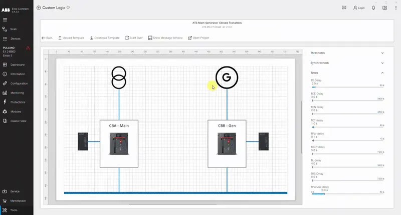
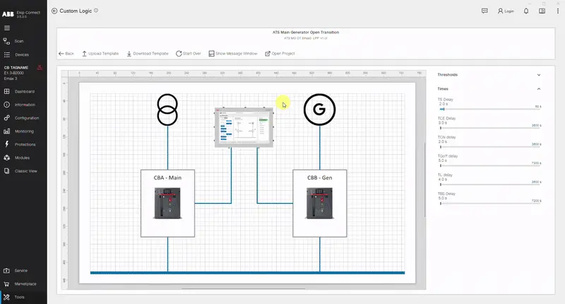
Access the ATS Templates by entering the custom logic tool, clicking the "Open Template" button and choosing the desired template to utilize.
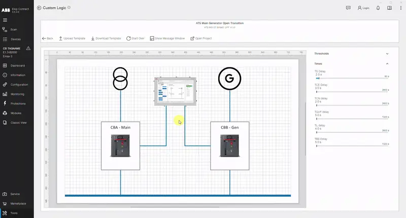
After opening the template, you can perform fine tuning of the Thresholds, Synchrocheck (if present) and Time Delays. After choosing the desired parameters, Connect to an Emax 3 circuit breaker and click on "Upload Template". Then choose the role you want the circuit breaker to assume in the ATS configuration, check the bill of materials and click "Upload".
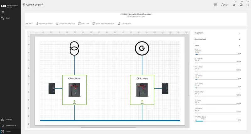
Afterwards, upload all the remaining roles to the respective circuit breakers, until all the breaker images in the template page turn green.
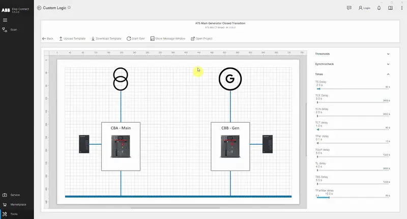
If you wish to analyze the custom logic project of the template or even utilize it as a starting point for your own projects, click on the "Open Project" button to access and modify it as desired.
If you wish to read parameters such as Thresholds, Synchrocheck (if present) and Time Delays from an Emax 3 circuit breaker in which the template was previously uploaded, connect with the device via USB Type-C, perform the scanning and click "Download Template". Repeat this operation on all the devices having roles of the same template.
If during the lifetime of the circuit breaker, the functioning of the ATS template is altered by mistake, download the template following the instructions explained above. If there is mismatch between the desired parameters and the ones present in the device, a Message Window will show in the bottom part of the view showing the exact altered parameters and suggesting the re-upload of the template.