The Networking tool is an all-in-one configurator for your circuit breaker. It enables the configuration of the desired communication network topology on devices by following a step-by-step user friendly wizard.
The most significant capabilities that the tool possesses are as follows:
Configuration of the Modbus TCP Radial network.
Configuration of the Modbus TCP Daisy Chain network.
Requirements
Access to the function
Unrestricted. For transfer to the device, Ekip Supply Evo Modbus TCP module is required.
Type of devices that support the function
Circuit breaker Emax 3
Device status
Connected and communicating to transfer the configuration to the device. Note: it is recommended to keep the circuit breaker in the open state during the transfer.
Type of connection with the device
Local connection: connection via USB Type-C
Modbus TCP Radial & Modbus TCP Daisy Chain
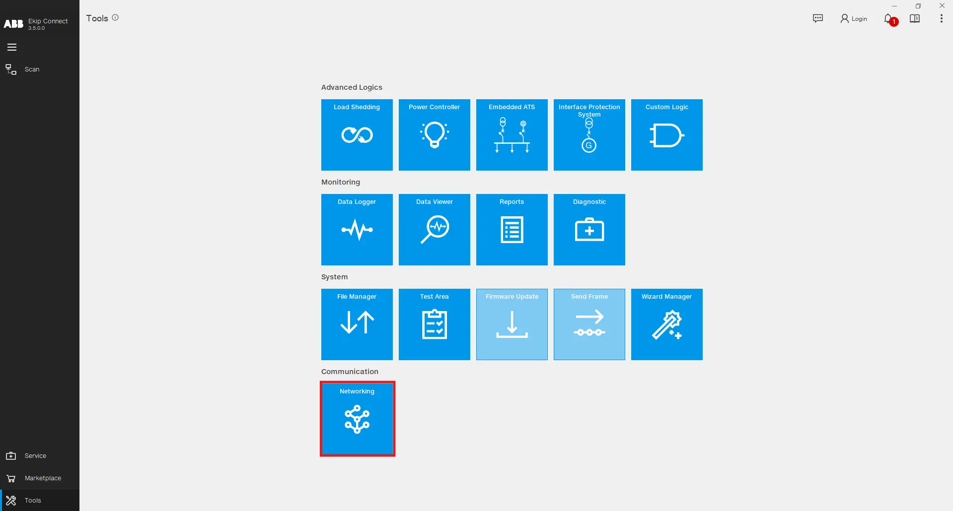
Open the Networking tool by clicking on Tools -> Networking
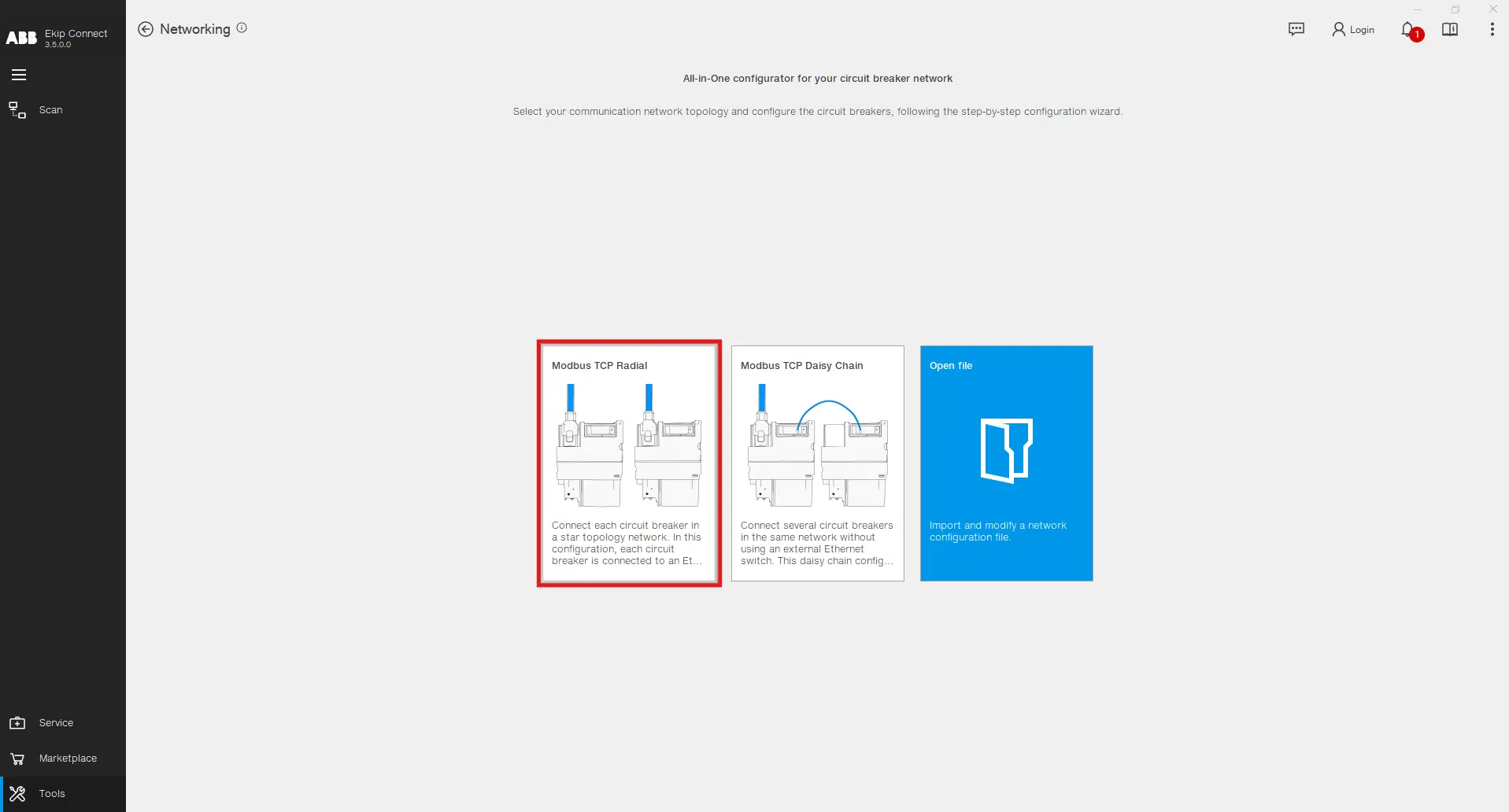
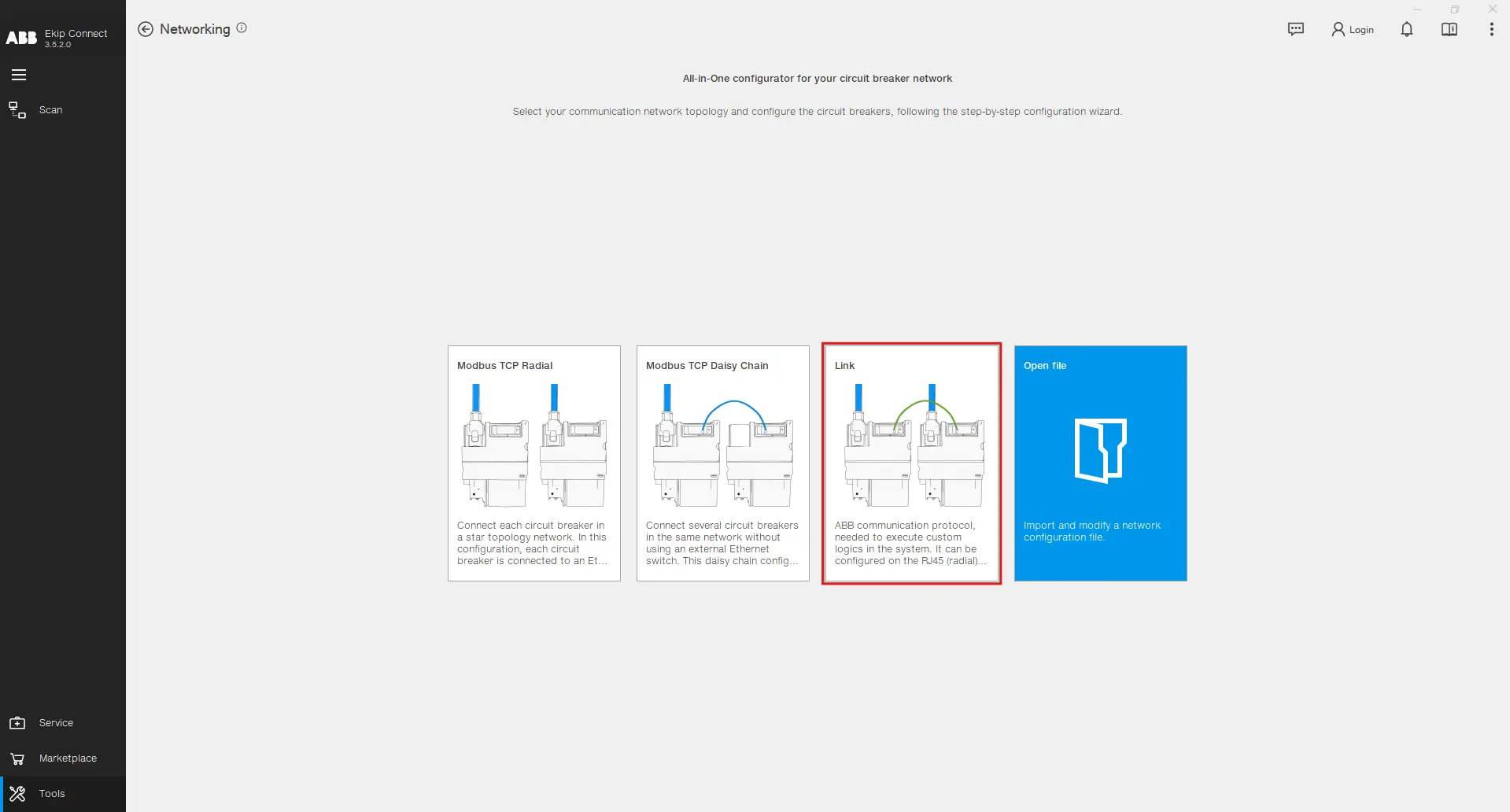
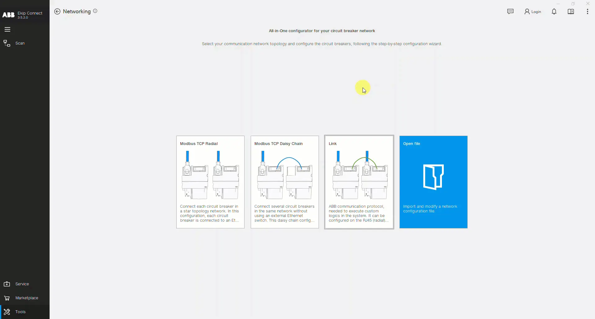
The tool's main page serves the purpose of introducing you to the possible configurations. Click on the Modbus TCP Radial configuration if you desire to connect each circuit breaker in a star topology while being connected to an Ethernet switch, ensuring centralized communication and control. This setup enhances network reliability and simplifies troubleshooting. Click on the Modbus TCP Daisy Chain configuration if you desire to connect several circuit breakers in the same network without using an external Ethernet switch. This configuration type reduces cabling complexity and costs, while still maintaining effective communication between devices.
Step by step Configuration
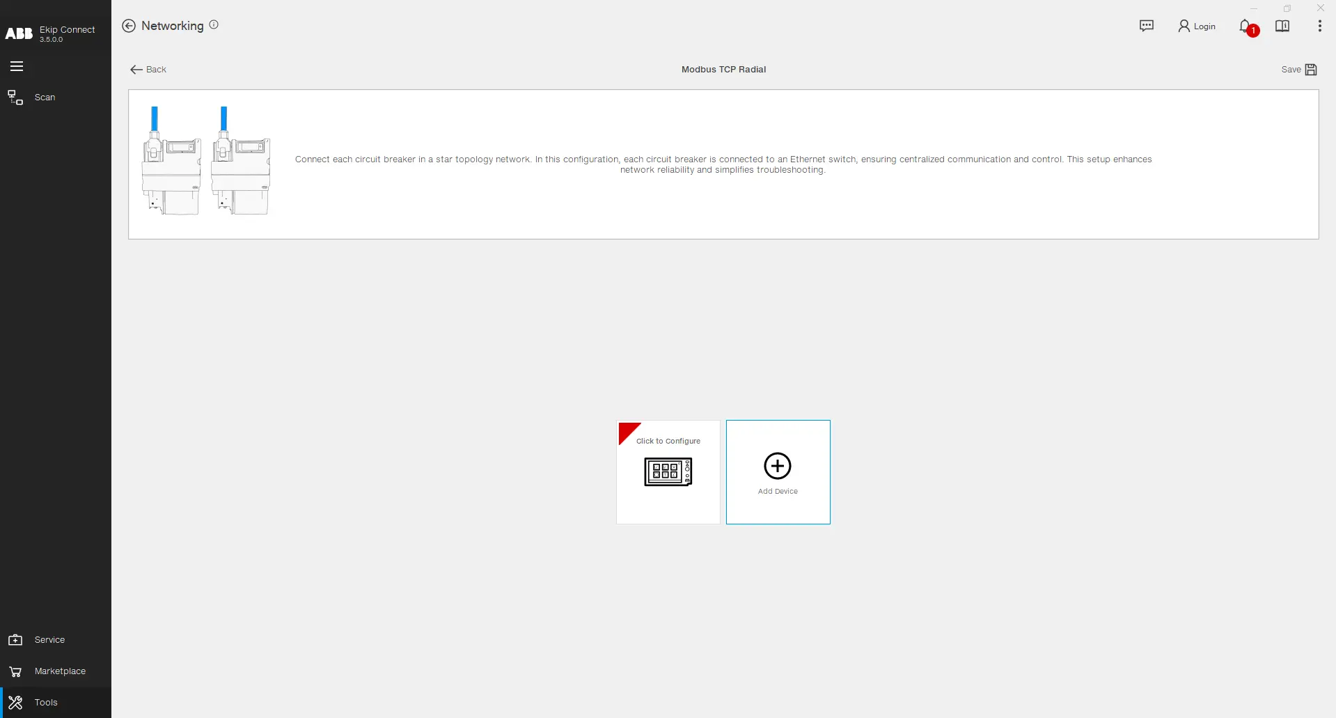
The Modbus TCP Radial and TCP Daisy Chain configurations are similar in terms of steps to execute on the Ekip Connect software. For explanation purposes, a detailed configuration is shown of the Modbus TCP Radial. Click on the highlighted tile to start the process.
Click on Add Device to insert a new device to your Modbus TCP network configuration and then click on the inserted Device to proceed with the configuration.
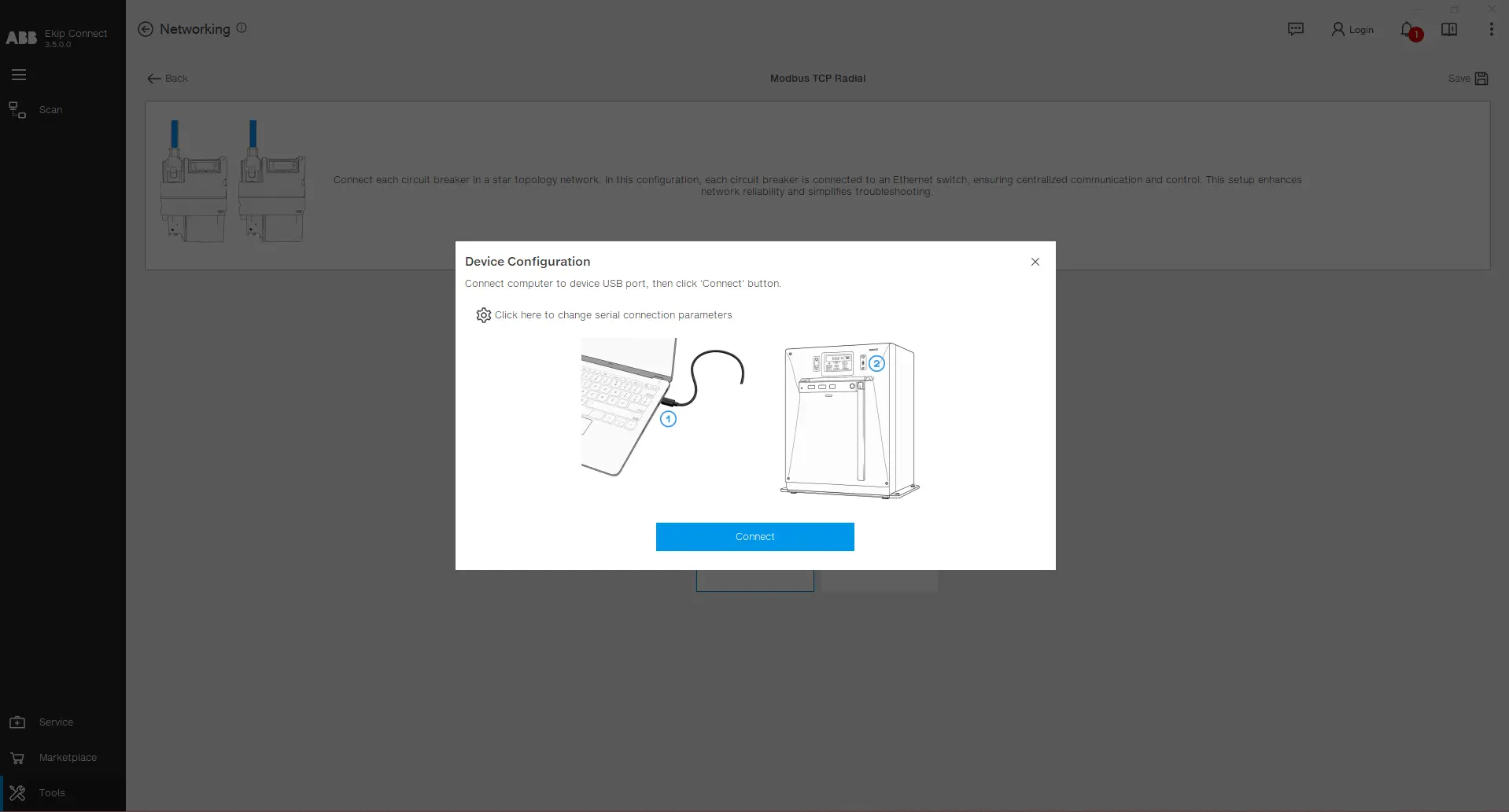
Connect the PC with the device via USB type-C, choose the right ports by clicking on the settings icon and then click on Connect.
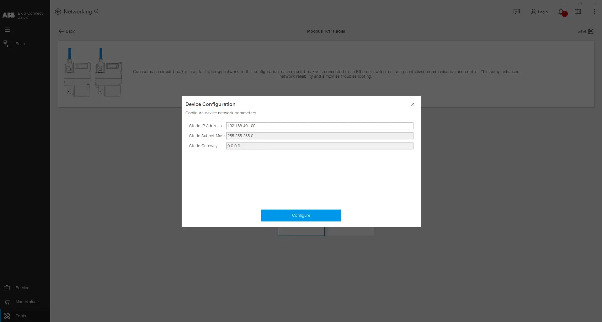
After being successfully connected to the device, the Static IP Address, Static Subnet Mask and the Static Gateway are read from the device and shown on the user interface. The value of the Static IP Address can be modified. After filling the desired values, click on Configure .
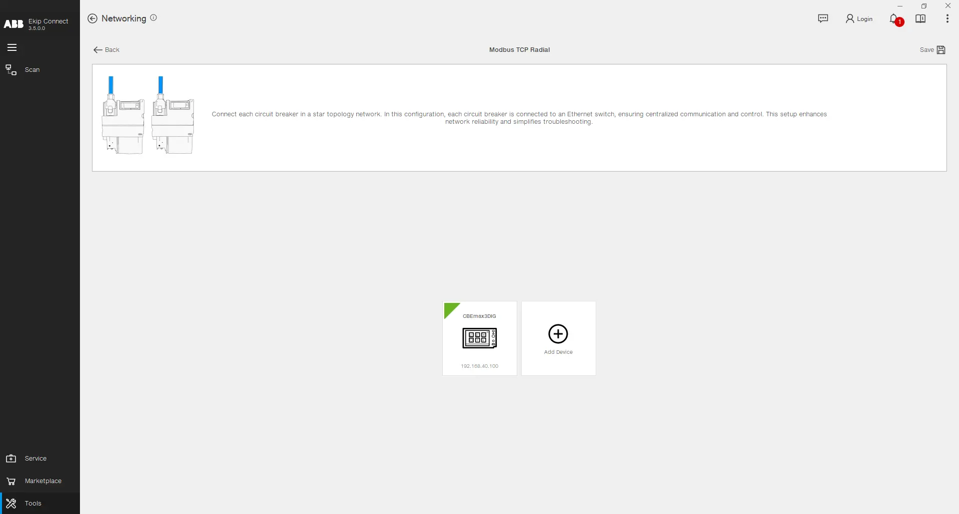
After the configuration is uploaded, you can notice that a green triangle appears on the tile of the configured device, alongside it's name and the static IP address chosen. You may proceed to add further devices to the configuration by repeating these steps in order to complete the full configuration of the network.
Link Network
Use the ABB communication protocol needed to execute custom logics in the system. It can be configured om the RJ45 (radial) or the 100-Base T1 (daisy chain). To access the Link configurator, click on the Link section in the Networking tool.
Step by step Configuration
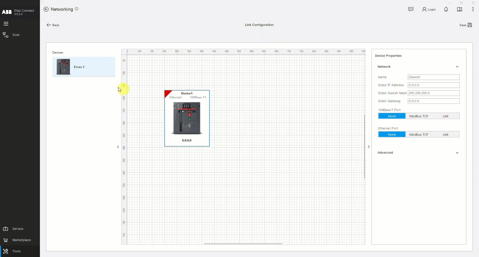
After clicking on the highlighted tile shown above, you will be presented with the design page in which you can build your network. The available devices are present in the left side, on the middle you can find the design sheet and on the right side, the selected device parameters are present. Start by drag and dropping an Emax 3 device in the design sheet.
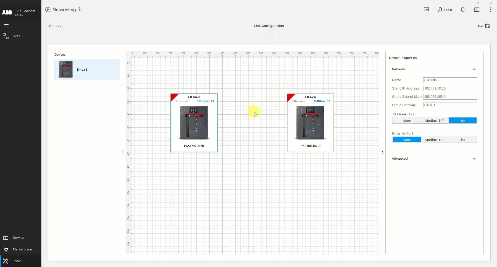
Drag and drop more devices and set up their Network Properties, such as the Name, Static IP Address, Static Subnet Mask, Static Gateway and the protocol for each port. The Link Network configuration is possible only if the Link protocol is chosen on at least one of the ports (100 Base-T1 or Ethernet).
Stretch an arrow from one device to the other to define a communication channel. Immediately after the arrow is in place, the Connection Properties appear. In this section you can choose what data should the publisher (the device from which the arrow starts) share with the subscriber (the device to which the arrow arrives). The data can be a single Bit or a Value (entire word of 2 bytes). The data chosen to flow in the bus are shown on the arrow for visibility purposes. You can create up to 15 communication channels from one device to others.
By clicking the device image and opening the Advanced section, you will be presented with the complete data flow on the selected device. It shows the variables in which the values and bits read from other devices are stored. You can then use these variables in your custom logic applications.
When all the parameters are chosen, the configuration can be uploaded to the respective devices. For Emax 3 devices, the upload procedure is possible via the USB Type-C connection. Connect your computer to the device and double click on its image in the design sheet of the Link Configuration page.
If you have previously configured the Modbus TCP protocol on the port in which you are now configuring the Link protocol, a warning message will show, explaining that the recently chosen protocol will be activated and the previous one will be deactivated. When the first configuration upload finishes with success, the red triangle present on the left side of the device image turns green. Repeat this process until all the configurations are uploaded into the respective devices. Finally, click on the Save button to save the Link Network configuration as a project in your computer to reuse it in other occasions.